Table of Contents
MAFComp Adjust (CombinedFT)
The MAFComp Adjust (CombinedFT) menu item is one of several tools you can use to help “dial in” your airflow settings. This particular item maps out and averages CombinedFT over a range of closed loop driving conditions to produce a set of adjustments to the current MAF compensation table. It's basically letting the ECU track how much adjustment it needs under various conditions and then moves that adjustment into the MAF compensation table.
This function probably helps most with a GM MAF setup run straight to the ECU using ECMLink's GM MAF integration option. That particular configuration produces a pretty large number of MAF sample points for fairly typical driving conditions (easily ranging from 500hz to 2000hz for simple idle and cruise conditions). So having a tool which helps establish a decent starting point can be very handy here.
Although this function probably helps a direct GM MAF setup more, it can still be useful with other configurations too.
STEP 1: Check Your Fuel Settings
You absolutely MUST make sure your fuel settings are already appropriate for your injector size, fuel type and base fuel pressure. If there is any deviation here, then the adjustments to airflow suggested by this function will simply include those fuel corrections as well! This can create a really confusing configuration if you aren't careful. So please review your global fuel and deadtime settings first to make sure they are at least somewhat reasonable for your setup.
STEP 2: Check For Closed Loop Operation
Make sure the car is able to run in closed loop mode. Look for a cycling FrontO2 sensor and a “1” in the ClosedLoop log item. It doesn't have to be running with fuel trims near 0% (that's the purpose of using this function after all). But it does need to at least cycle in closed loop mode on its own. If it does not, you need to make some manual adjustments first to at least get it running in closed loop.
A good understanding of CombinedFT and fuel trim in general will help a lot with your understanding of this function.
STEP 3: Data Capture
Add the following log items to your captured values (F10): CombinedFT, MAFRaw and ClosedLoop
Make sure the engine is at full operating temperature. You don't want to mess with coolant based variations at this point. You want to stabilize everything you can first and then adjust based on the one variable left (presumably airflow variation).
Once you're satisfied that the requirements above have been met, you're ready to grab a datalog. Let the car idle for about a minute. Then go drive. Try to keep the car in closed loop mode as much as possible (more on that in the advanced section).
STEP 4: Run the Adjustment Tool
When you're done, stop the log and click on the MAFComp Adjust (CombinedFT) menu item (right click in the graph window to get this menu item) to see what the application comes up with. Review this, smooth the points as you'd like, extend the points to cover areas where you did not collect data and then hit “Save to ECU” when you're done.
NOTE: You're basically changing the very data long term fuel trim was previously based on. So if you're making fairly large changes to MAF compensation, you should consider resetting the long term fuel trim values using the “Reset fuel trims” menu item in the ECU menu.
Advanced Usage
Because this function operates only during closed loop mode, it's handy to try to extend closed loop mode as much as possible so that you get a wider range of data in your logs. This will produce a larger number of auto-adjustments to the airflow curve for you.
There are several ways you can extend closed loop conditions. The easiest of which is to simply edit the DirectAccess tables that control when open loop is triggered. By moving those open loop trigger points “higher”, you extend the conditions under which closed loop mode will be maintained by the ECU.
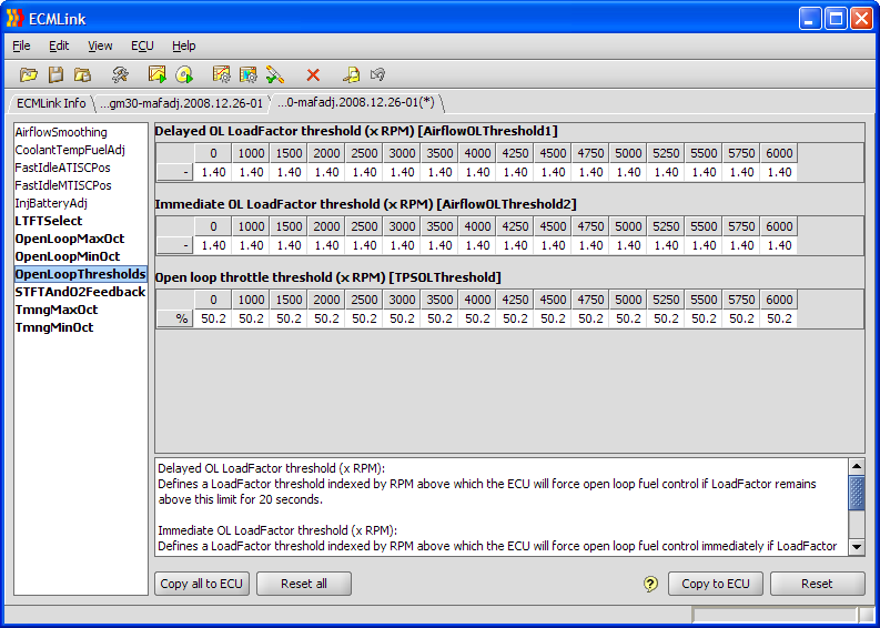
The image below shows a fairly typical setup for the various open loop threshold tables you can use to extend closed loop mode for this test. Keep in mind what you're doing here, though. You're basically telling the ECU to maintain stoich air fuel ratios under more load (LoadFactor) and with more throttle. This could very well produce a hotter mixture than you'd like to maintain for any lengthy period of time. So monitor EGTs if possible or if not, just try not to stay under high load/closed loop mode for very long.
With that table in place, you can grab a datalog with a bit more load variation. Personally, I like to find a nice hilly area and apply light throttle to vary LoadFactor between 0.9 to 1.3 while maintaining closed loop operation. This driving combined with the typical flat road driving (with LoadFactors around 0.6-0.9), combined with typical idle and free rev (LoadFactors around 0.3-0.4) really produces a good set of data for this function.
Sample Calibration
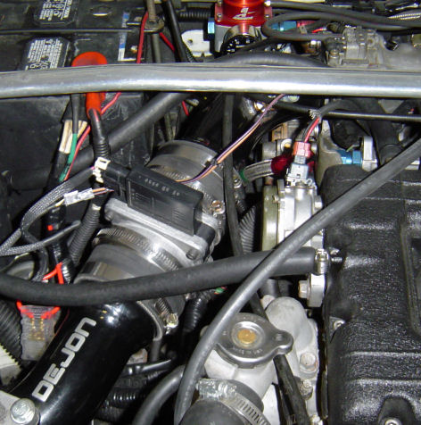
I'll walk through a sample calibration of my own car below. This is a 1995 AWD Talon with 850 injectors running E85 and a GM 3“ MAF connected to the ECU. The MAF is installed just before the throttle body using upper IC piping that has flared 3” ends as shown below.
Download the datalog below to review the initial drive cycle (20 minutes or so) and setup. The things to note include the global fuel setting and the MAF compensation.
Initial drive cycle and setup log
Global fuel is set appropriately for 850s on stock base pressure running E85 using the following formula:
100% E85 Global Adj = 1.5 * Stock Injector Size / New Injector Size - 1
100% E85 Global Adj = 1.5 * 450 / 850 - 1 = -0.206 or -20.6%
Initial MAF compensation was left zeroed out because my car runs normal closed loop operation with the 3“ GM MAF without any additional compensation needed. Your car may very well be different! You may need to adjust the global MAF compensation a bit before starting out. Just get the setup close enough that it will run closed loop operation without maxing the fuel trims.
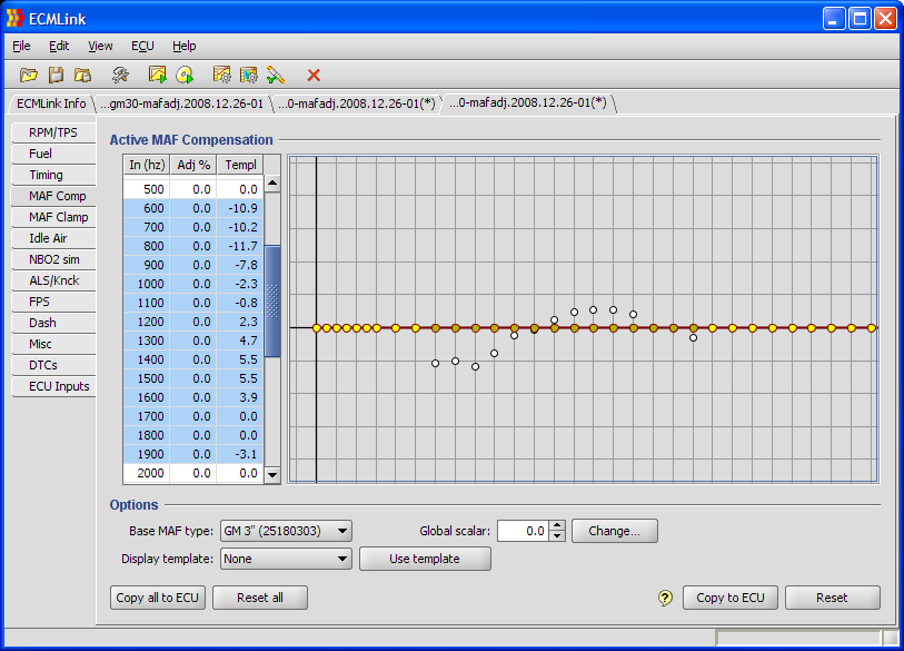
Once that drive was done, I did the “MAF Adj: CombinedFT” function and got the following results. The white dots below are the “suggested template” values produced by this function.
I have selected (highlighted) the data points for which the function provided some adjustments for clarity. Looking at these points, I'm pretty happy with the values. Nothing is maxed out and there aren't huge variations from point to point. So I'm just going to click “Use template”.
I'm also going to extend the lowest adjustment point to cover the areas where I was not able to collect any data. My car idles around 600hz with the GM 3” MAF. So it's hard to produce much closed loop data below this point. So we're going to assume it's somewhere around the 600hz point just in case the car ever does end up below that point.
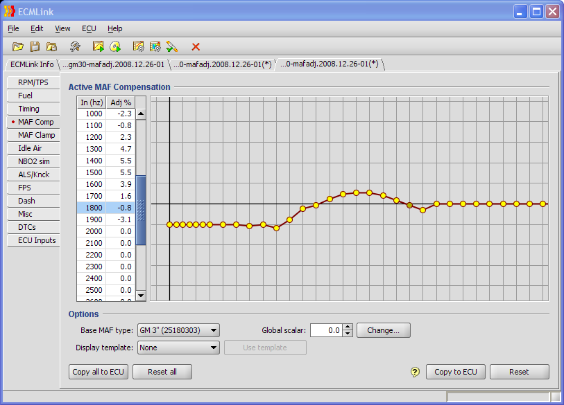
Looking at the 1700 and 1800hz points, I feel a need to tweak them a bit. They're just flat where as the points before and after are not. So I'm going to slightly adjust those two points so that they make a more natural transition between the 1600 and 1900 points. After doing that, you can see the new results below.
So what about the points above the 1900hz? Well, that will involve some sort of wide open throttle tuning and will need to be covered in more detail in a different article using a different approach. For now, what I did was to make one quick pull in that datalog above. You can find it around 1194 seconds into the file.
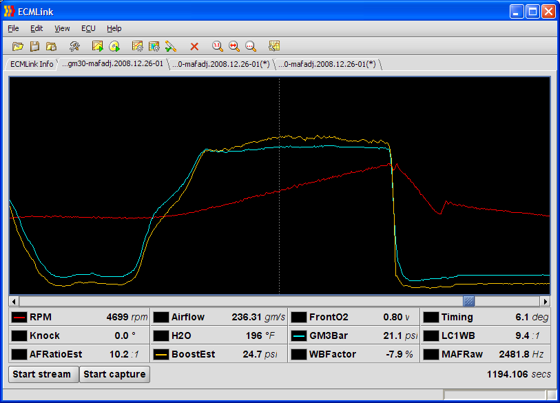
What you see in that log section is BoostEst lined up with measured boost (GM3Bar). Notice how the two slowly separate for a short period of time and then the difference between them stabilizes around 4700 RPM (2481 hz). I'm going to pick that stabilizing point as my next adjustment index.
BoostEst is 24.7psi at that point and GM3Bar is reading 21.1psi. But you have to work in absolute pressure when trying to calculating an adjustment:
Adj = (21.1 + 14.7) / (24.7 + 14.7) - 1 = -0.091 (or -9.1%)
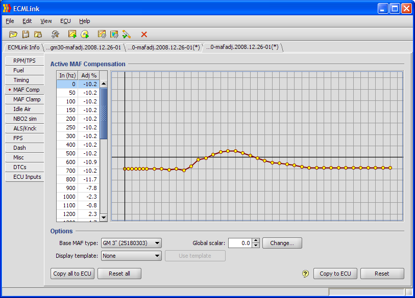
So I'm going to move the 2500hz adjustment point (and all the others above that) down to around -9.1%. Then I just need to interpolate a smooth line between the 1900hz point where we had some data before and the 2500hz point where we have new data now. The final results are shown below.
This is my new, final configuration. To get that centered nicely, I'll click the “Change…” button next to “Global scalar” field and then click “Auto Adj” on the dialog that pops up. The application will center the current set of adjustments for me and produce an appropriate global scalar value. I'll then do an “ECU→Reset fuel trims” and go drive. Everything should line up much better now.
