This is an old revision of the document!
Table of Contents
ECU-based Boost Control Overview
ECMLink's boost control mechanism is modeled after the factory implementation provided on 1995+ DSMs and Lancer EVOs. The most notable difference being that ECMLink's implementation provides gear-based control rather than a single curve that applies all the time.
The basic operation goes like this:
- Look up a base duty cycle from the Base Duty Cycle table based on gear and engine speed (RPM)
- Adjust this value by some amount based on how far away current boost is from desired boost
This sounds pretty simple and it really is, but once you start picking about the phrases, you'll see it's a bit more involved than it might seem at first.
A sample screen shot is provided below for reference in the following sections.
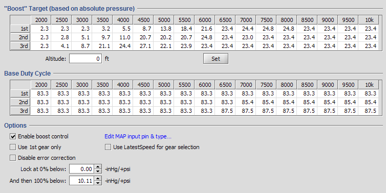
Base Duty Cycle
The Base Duty Cycle table defines the starting point for the boost control solenoid. At any given RPM and in any particular gear, the ECU references this table to get a “base” value it'll use for the boost solenoid output.
If error correction has been disabled, then this value is the final value the ECU is going to use and your turbo will build whatever boost it just happens to build for the given wastegate duty cycle. You can use this mode of operation during setup and dialin to find where you setup naturally needs to be to build the boost you're looking for.
If error correction has been enabled, then the ECU references the Boost Target table to determine (for the same RPM and gear) what boost it should be trying to achieve at that moment. It then adjusts the base duty cycle according (up or down). It tracks this adjustment with a “trim” value, similar to the short term fuel trim. The final duty cycle used by the ECU is basically:
Final DC % = (base DC %) + WGSTrim
The WGSTrim value is a loggable variable.
Boost Target
The Boost Target table defines the manifold pressure the user is expecting to achieve at a given RPM/gear combination. The ECU uses this value when error correction is enabled to adjust the base duty cycle value up or down as necessary in an attempt to get measured boost to match the target value.
Measured boost is determined from the configured MAP sensor input on the ECU Inputs tab. You MUST configure this input first before the error correction process will work. You do this on the ECU Inputs tab using the fields shown below.
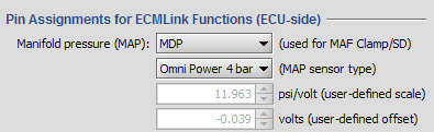
The ECU will compare current boost reported on the specified pin using the specified MAP sensor scaling against the target boost pulled from the Boost Target table to determine a boost “error”. How far off the current boost is from the target boost will determine how much error correction is applied to the current duty cycle (which may have been corrected already by some amount from a previous pass through this correction process).
WGSErrorCorr - Direct Access table
The table used to define how much error correction to apply is found in the Direct Access tab. It's listed there as WGSErrorCorr. It defines a correction amount (expressed as duty cycle percentage) to apply to the current duty cycle based on a boost pressure difference. A bigger difference (larger error) typically results in a more aggressive (larger) adjustment to the base duty cycle.
If you get oscillation or you want faster response, you can decrease or increase (respectively) the corresponding entries in the WGSErrorCorr curve.
Altitude correction
The pressure sensors used by ECMLink are all absolute pressure sensors because absolute pressure is far more useful to the ECU than “boost”. But the user is more familiar with “boost”, so ECMLink provides an altitude correction factor to roughly translate absolute pressure to boost.
