This is an old revision of the document!
Table of Contents
SD VE Adjust (SDRatio)
This page describes an adjustment tool in the ECMLink application that helps to dial in your speed density (SD) VE table based on data collected from a mass airflow sensor. If you do not plan to run speed density mode with your car or you do plan to run SD but do not have a mass airflow sensor installed for dial-in, then this page is completely useless to you and you should ignore it.
If you're not even sure what speed density mode means, then read up on our Speed Density 101 page.
The following assumes that you have already configured your ECU and installed the sensors for speed density operation. If you have not, please read our ECMLink - Speed Density Setup page. In particular, you must have your manifold absolute pressure (MAP) sensor installed and configured in the ECU Inputs tab of the ECMLink application. And you must have the intake air temp sensor installed and connected to the intake air temp input of the ECU (IAT sensor exception listed below in the NOTES section related to using a stock mass airflow sensor).
STEP 1: Mass Airflow Sensor Calibration
This function basically tries to configure your SD table to produce the same airflow values as your mass airflow sensor. So it stands to reason that you want to make sure your mass airflow sensor is calibrated very well first.
The MAFComp Adjust (CombinedFT) page describes an excellent process for dialing in your mass airflow sensor. Please read through this page carefully and make sure your mass airflow setup is calibrated as well as you can get it before attempting to use the SD VE Adjust (SDRatio) function.
STEP 2: Data Capture
To use this tool, you need to capture some data from your ECU while you drive around on the mass airflow sensor.
 Add the following log items to your captured values (F10): SDRatio and MAP sensor. (If SDRatio does not appear as an item available for capture, you don't have the MAP sensor's input pin assignment configured in the display items on the ECU Inputs tab, and you need to do so.)
SDRatio and engine displacement: It's very important to make sure SDRatio's engine displacement preference is set correctly to match your actual engine. Do this by double clicking on SDRatio in the graph legend.
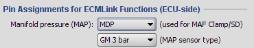
The MAP sensor you want to log here is the one you have already configured in your Manifold pressure (MAP) field on the ECU Input tabs. An example of this is shown here. More details on configuring and installing this sensor can be found on the ECMLink - Speed Density Setup page.
When attempting to initialize the SD VE Adjust (SDRatio) tool, the application will check your ECU Input tab to locate the MAP sensor. It will then attempt to find this sensor in your datalog. Using the image above as an example, you would want to log the GM 3-bar sensor attached to the MDP input in order to use this function.
While running off the mass airflow sensor, you basically just drive around logging the data above (SDRatio and MAP sensor) in your datalog. Try to drive under a variety of conditions (idle, cruise, wide open throttle). I like to locate a nice hilly area so I can vary throttle position, RPM and boost to generate the data I'm looking for.
STEP 3: Run the Adjustment Tool
When you're done, you right click in the graph area and select the SD VE Adjust (SDRatio) menu item. The application will then make a number of suggested changes to your SD VE table. You will definitely want to smooth and tweak this data a bit to make it “look nice”. The application is just going to slap numbers into cells that it has data for. You'll need to extrapolate that data a bit to areas where you don't normally drive if you want to make the table work well in unexpected conditions.
NOTES AND TIPS: Things to Keep in Mind
Stock (Mitsubishi) MAF sensor
Running on a stock Mitsubishi MAF sensor is a great idea for dialing in SD because it tends to produce a very accurate signal. However, the problem is that a stock sensor uses the intake air temp input to the ECU for its own purpose. You can not simply disconnect this and connect your own GM IAT sensor. Your airflow readings WILL be off.
In order to use a stock MAF sensor in conjunction with the SD VE Adjust (SDRatio) tool, you must basically disable speed density's use of the air temperature sensor for airflow calculation. You do that by setting the entire SDTempWeighting table (found on the Direct Access tab) to zero across the board.
If you do not do this, the ECU will try to treat the factory MAF sensor's air temperature reading as a GM IAT sensor located in the upper IC (or intake manifold). The results will be an inaccurate calculation of the SDRatio value and inaccurate adjustments to your SD VE table.
The downside, of course, is that if you disable the air temp sensor for speed density operation inside the ECU, then you need to make sure your air temperature reading while doing your calibration drive is fairly reasonable (say between 50-90F). A good working intercooler and some careful attention to your right foot will help immensely with this too.
GM MAF sensor
If you're running a GM MAF sensor, there is one special case to consider. The GM MAF Translator provided by Full Throttle and some of our earliest GM MAF cables powered the GM MAF off sensor ground (available from the original factory MAF connector). We realized later that this was not a good idea because the GM MAF draws enough current through sensor ground to produce a voltage offset on all the other sensors powered off sensor ground! That includes the TPS and, more importantly for SD work, the manifold pressure sensor!
As long as the GM MAF stayed connected, the offset simply remained constant and you would never really notice much effect. But when you switch to SD, you fully expect to disconnect the GM MAF sensor and that's when the offset makes a difference! Suddenly the pressure sensor output changes relative to what it was when you were dialing the SD setup in using your GM MAF sensor.
To ensure that this isn't a problem, you have to use one of our newer GM MAF cables that provide a separate power wire for the GM MAF's grounding point or you need to modify our older GM MAF cable (if that's what you have) to add this wire. If you're running a GM MAF Translator device, you could probably do the same ground wire modification as we recommend for our older GM MAF cables, but I can't guarantee that.
