Table of Contents
LC-1/LM-1 Installation Example
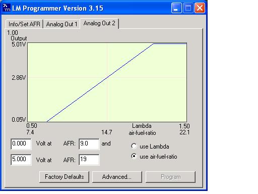
The Innovate LC-1 and LM-1 wideband kits are programmable units. That means the mapping of voltage output to A/F ratio can be changed by the user. Which means there's no default LC-1 or LM-1 item in DSMLink to datalog. So what we suggest you do is to program the output to mimic another device that we do support. Typically this would be the linear TechEdge output that has 9:1 mapped to 0v and 19:1 mapped to 5v. Then you would datalog this as the linear TechEdge (TEWBLin).
NOTE: The most recent versions of the ECMLink laptop application include a native Innovate datalogging routine that uses the default mapping setup by Innovate in the LC-1. There is also now a generic “linear wideband” display item you can use instead to define your own mapping. The instructions below have you map the LC-1 output to match the TechEdge linear, which is fine too. But if you want to skip that step entirely, you can just use ECMLink's LC-1 log item instead and leave the default LC-1 mapping alone. You can also consider using ECMLink's (V3) Narrowband Sim function instead of running two separate outputs from the LC-1 into the ECU.
Version Check: Please take note of the version of LM Programmer shown in the screenshots. There are newer versions (v3.19 and 3.27) that are shipping with the units that Innovate knows does not function as it should. For some reason, they do not mention this anywhere. The easiest way to determine if the version you have works is to make the changes below, click the Program button, and then go back in and see if the settings were retained. The most recent version does not hold your changes. The latest known working version is v3.15. Until Innovate provides a fix for this, you can download the older v3.15 software here:
https://www.ecmtuning.com/images/forums/lc1install/LMConfig315.exe
Details
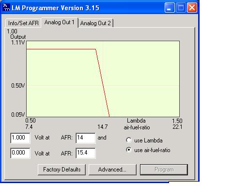
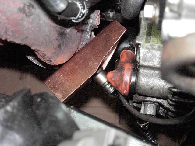
Scott McIntyre provided the following information on our user support forums for his install of the LC1 into the front O2 sensor bung. He uses the kit's narrowband output (analog 1) to drive the front O2 input for closed loop operation and then feeds the kit's analog 2 output to the rear O2 input on the ECU for datalogging wideband A/F ratio. The following are pictures he posted of his install procedure.
NOTE: Our V3 ECMLink product actually provides for narrowband simulation inside the ECU. This allows you to simply connect the 0-5v analog output to the ECU and let the ECU simulate the narrowband signal internally. This frees up an additional logging input to the ECU as a result. More details can be found on our Narrowband Sim page.
Analog out configuration
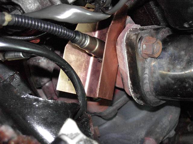
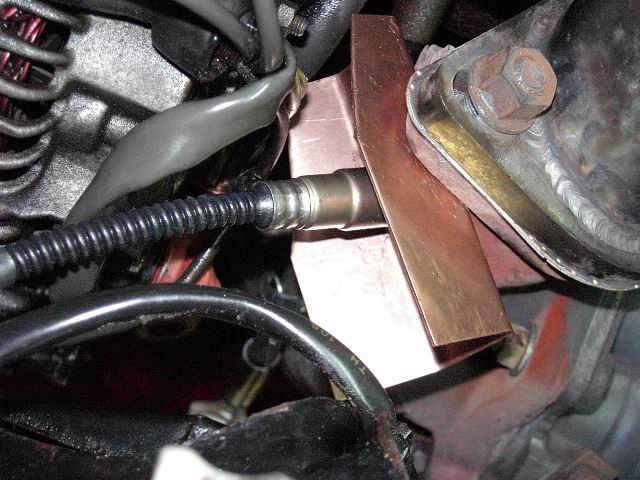
Copper heatsink fabrication
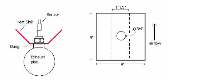
To aid in heat dissipation when the wideband sensor is installed in the front O2 location, a copper heatsink can be constructed. The following is taken from the Innovate install manual.
Use a 4“ x 4” (10cm x 10cm) sheet of copper sheet metal 14ga (1.5mm thick). Drill a hole in the center with the same diameter as the oxygen sensor threads (about 3/4“ or 19mm). Fold the sides up 45° and mount it between the sensor and the bung like you would a big washer. Orient it such that the sides are exposed to good airflow.

