This is an old revision of the document!
Table of Contents
ECMLink - Speed Density Setup
This page describes the basic process for getting your car setup for speed density operation with ECMLink. If you need a more general speed density tutorial, then the Speed Density 101 page may be what you're looking for. In fact, we're going to assume you already know everything off that page as we discuss items below. So it might be a good idea to read over it even if you're already pretty familiar with SD in general.
The basic process for getting a new SD system up and going is listed here. More details follow in the sections below.
- Connect IAT and MAP sensors to ECU
- Configure ECU for SD operation
- Dial in the VE table for your car
Connecting the Sensors
The first step is to connect your sensors to your ECU. You'll need a GM IAT sensor and an absolute pressure sensor. The following two sections list the supported sensors. A good source for the GM sensors might be GM Parts Direct. We also really like the EFI Connection for GM connectors.
For additional wiring and/or pinout information, please refer to our ECU Wiring Information page.
Air temperature - GM IAT/AEM IAT
| Sensor | Desc/part number |
|---|---|
| GM IAT | GM Intake Air Temperature P/N 25036751, pig tail 12102620 |
| AEM IAT | The exact same as the GM IAT |
You must connect your IAT sensor to the ECU's IAT input. This is the only input that's compatible with the speed density logic inside the ECU.
You'll want to use pin 72 (red w/blue stripe) on a 2G ECU harness or pin 8 (green w/orange stripe) on a 1G ECU harness for this. Or, more likely, you'll want to use those wires off the MAF harness under the hood since that's where the IAT sensor is actually being installed. ![]() The wire colors are the same on the MAF connector as on the ECU harness.
The wire colors are the same on the MAF connector as on the ECU harness.
The IAT sensor has two wires coming out of it. Either wire can be connected to the ECU's IAT input.
The other wire should be connected to the ECU's sensor ground. That would be pin 92 (black) on a 2G ECU harness or pin 24 (green w/black stripe) on a 1G ECU harness. This can also be pulled from the MAF connector under the hood. The wire colors are the same on the MAF connector as on the ECU harness.
Absolute Pressure
| Sensor | Desc/part number |
|---|---|
| GM 3-bar | GM 3-bar P/N 12223861, pig tail 15305891 |
| GM 3.3-bar | GM 3.3-bar P/N 9373269, pig tail 88987997 |
| AEM 3.5-bar | AEM 30-2130-50 (50 PSIA / 3.5 Bar) |
| AEM 5-bar | AEM 30-2130-75 (75 PSIA / 5 Bar) |
| Omnipower 3-bar | MAP-MIT-3BR (3 bar) |
| Omnipower 4-bar | MAP-MIT-4BR (4 bar) |
You wire up a pressure sensor much like you wire up any other aftermarket sensor for logging. The details of which can get complicated because there are several different inputs you can use and several different sensors. So it's hard to write up a COMPLETE how-to on this.
Our Aftermarket Sensor Install page is a good starting point. That page links to several other useful pages, including this example install of a GM 3-bar sensor on the 2G MDP input.
The basic process involves the following steps:
- Select an available ECU input you want to use
- Remove any existing sensor connected to that input
- Install the new sensor, providing any necessary power and ground connections to it
- Connect the sensor's output signal to the ECU's input wire you selected in step 1
- Connect the sensor's air fitting as intimately as practial to the intake manifold. Avoid long, narrow hoses, tees and small-diameter fittings that slow the sensor's response.
Using our GM MAF Cable
If you have our GM MAF cable already, GREAT! You can use the breakout points provided on that cable to connect your MAP sensor and IAT sensor directly to the car's wiring harness. Our GM MAF IAT/Baro page describes how to do this.
Configuring the Software
First, make sure you have installed the latest version of our application off our downloads page. You'll want at least v3.18.182. Anything older than that may not even connect with your ECU.
Once you have installed the latest software, you can enable speed density operation by defining three things:
MAP Sensor Location and Type, BaseMAF type, and Engine Displacement
MAP Sensor Location and Type
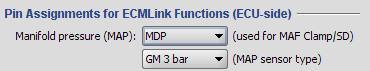 Because you can connect your MAP sensor to any number of ECU inputs, you have to tell the ECU where it can find this sensor in order to use it for SD operation. You do this on the ECU Inputs tab in the “Pin Assignments for ECMLink Functions (ECU-side)” area.
BaseMAF Type
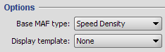 Tell the ECU to ignore incoming MAF data and calculate it from speed density data instead. You do that on the MAFComp tab by selecting “Speed Density” as your Base MAF type.
This step must be done before the application will allow you to set the engine displacement.
Engine Displacement
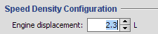 The final step is to set the engine displacement. On the Speed Density tab, there's a text box where you need to enter your engine displacement. The ECU uses this information to correctly calculate airflow. More information on this process is outlined in the SD101 page.
Airflow Smoothing
 Mass airflow sensors used by the DSM ECU tend to require some “smoothing” or “averaging” inside the ECU of their output signal. This type of averaging actually delays the signal used by the ECU (since it's averaged out, a real change in airflow takes a little longer to register inside the ECU). Fortunately, mass airflow sensors respond very quickly to changes in airflow rate, so this delay isn't a major problem and the ECU is dialed in to account for it anyway.
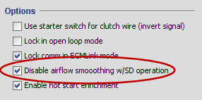
But because pressure sensors tend to respond more slowly to pressure changes than mass air sensors respond to airflow changes, you have to disable this smoothing. Otherwise you end up terrible throttle response as the ECU is unable to respond quickly enough to a change in throttle position.
To disable airflow smoothing, just check the “Disable airflow smoothing w/SD operation” checkbox on the Misc tab as shown in the screen shot here.
Throttle Tip-In
If you still notice some slight hesitation with throttle changes even after disabling airflow smoothing factors, you may need to adjust your base throttle tip-in. You can do this in Direct Access (F6) using the BaseTipInTPSAdj table.
This table is indexed by rate of change of throttle position. Because this value isn't at all obvious, you need to log TPSDelta to see which rows in the BaseTipInTPSAdj are being used at any given point in your log. TPSDelta is the value used as the raw index into the BaseTipInTPSAdj table.
If you increase values in the BaseTipInTPSAdj, you will get a larger “squirt” of fuel as you increase throttle position. Do this if you notice some hesitation when you jab the throttle once you enable SD operation.
Dialing in the VE Table
This is the “fun” part of a new SD installation. Luckily, there are a several tips and helpers that can make this process pretty painless.
- SD VE Adjust (SDRatio) - If you have the option of running on a mass airflow sensor while you dial in your speed density VE table, then definitely do so. This is the adjustment tool you'll use.
- SD VE Adjust (CombinedFT) - After you've got an initial SD VE table (either the default one provided for you or one derived from a mass airflow sensor), you can further refine closed loop behavior using this tool.
